Comprehensive Paint Coating System with 3-Can RTO, Multistage Heat Recovery, and Curing and Bake Ovens
- Home
- Case Studies
- Comprehensive Paint Coating System with 3-Can RTO, Multistage Heat Recovery, and Curing and Bake Ovens
Comprehensive Paint Coating System with 3-Can RTO, Multistage Heat Recovery, and Curing and Bake Ovens
The Challenge
In painting or coating industrial products, such as metal coils, pipes, drums and the like, it is well known to use gas-fired ovens which will dry painted or coated products and yield a gaseous effluent containing a substantial amount of combustible constituents such as hydrocarbons. Such ovens may be operated at low temperature, intermediate temperature, or high temperature, depending upon the type of coating and the particular stage in the processing of the coated product. It is common in the operation of industrial ovens to vent the gaseous effluent from individual ovens into separate fume incinerators.
The use of a Regenerative Thermal Oxidizers with Secondary & Tertiary Heat Recovery in the industrial oven applications, especially baking or curing ovens for painted or coated products, coating oven effluents, coating rooms, spray booths, and the like to improve energy usage and safety for plant operations while maintaining air pollution control requirements.
The Solution
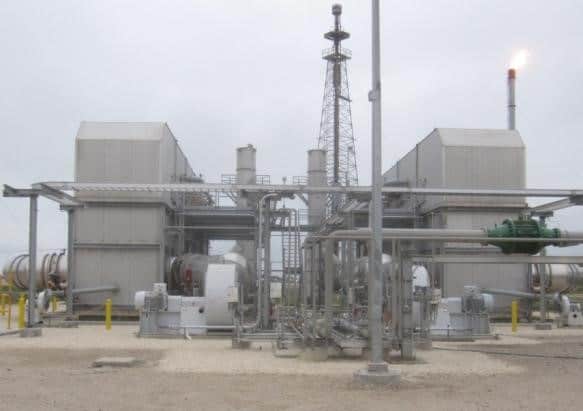
Regenerative Thermal Oxidizers (RTO) are a highly energy-efficient and effective means of reducing and controlling air pollution. The regeneration principle operates around multiple energy recovery chambers in use on the system, which are the housings for the ceramic heat recovery media. The ceramic heat recovery media acts as a primary heat exchanger for the system. The multiple chambers (3 Chambers in this example) operate under a “swing bed” absorption principle: which is the principle of energy transfer through multiple beds by the use of flow reversal. In the use of this principle with ceramic stoneware, the process is called regeneration. As the primary process exhaust stream containing volatile organic compounds flows through the first bed of ceramic media, the exhaust stream absorbs the thermal energy stored in the ceramic media mass, which pre-heats the primary process exhaust stream. The process exhaust stream then enters the RTO combustion chamber, where thermal energy from the burner is added to maintain the system operating temperature or if the process contains sufficient heat release no supplemental energy needs to be added by the burner. The RTO combustion chamber is typically designed for 1.0 second residence time; however, depending on the permitted emission requirements and/or the type of VOCs being oxidized may require a different residence time. After the process exhaust temperature has been elevated in the RTO combustion chamber, the oxidized (“clean”) process exhaust stream then passes through a second energy recovery chamber. During this time, a third energy recovery chamber is being purged.
At the exhaust stream passes through the energy recovery chamber, the “cold” ceramic media mass absorbs the thermal energy of the exhaust stream and subsequently stores the thermal energy for the reverse flow sequence of operation of the system. Once the thermal energy of the first chamber has been depleted through the absorption of the incoming primary process exhaust stream, the flow through the system is switched. This results in the incoming VOC-laden process exhaust being directed through the previous absorption chamber which has been saturated with thermal energy, and the oxidized (“clean”) exhaust stream now going through the previously purged chamber.
The oxidized (“clean”) process exhaust air stream then exits the ceramic bed and enters an outlet manifold that supplies this treated air stream to the indirect Secondary Heat Exchanger. This Secondary Heat Exchanger then transfers heat indirectly from the “clean” RTO outlet exhaust to a secondary process stream which may consist of fresh air or a second plant exhaust stream (e.g. in the finishing industry, this may be Coater Room exhaust containing low VOC concentrations). This secondary process stream can then be used to supply hot air back to a plant process (such as Curing Ovens). This significantly reduces the required heat to be supplied by the Oven burners reducing gas use-age and Oven burner generated NOx emissions.
Final temperature control at the point of use inside of the plant is regulated through the use of flow control valves. Fresh Air or the secondary process stream uses a secondary heat exchanger fan controlled by a variable frequency drive (VFD) as the motive force. Certain system embodiments may also include an auxiliary burner configured to further raise the temperature of the secondary process stream (previously pre-heated by the secondary heat exchanger) prior to being supplied to the plant process. If excess pressure/flow is being supplied back to the plant from the secondary heat exchanger, then a pressure relief damper returns the excess flow back to the inlet of the RTO.
Other system embodiments may comprise a hot gas bypass conduit and damper(s) fluidly connecting the combustion/retention chamber and the RTO outlet manifold by a mixing chamber. In processes that contain large variations in VOC concentration, this allows the RTO to be designed for a higher heat recovery to minimize fuel consumption during low VOC loading conditions. When levels of VOC concentrations increase, and the primary heat recovery is too high, the hot gas bypass system opens allowing the “excess” heat to be displaced from the combustion chamber. The mixing chamber may then supply this blended “clean” process exhaust air stream to the inlet of the Secondary Heat Exchanger.
After the oxidized (“clean”) process exhaust air stream exits the Secondary Heat Exchanger, this treated air stream then enters the indirect Tertiary Heat Exchanger. The Tertiary Heat Exchanger is fluidly connected to a water source conduit, a coil, and a heated water outlet conduit. The air-to-water heat exchanger recovers a portion of the remaining waste heat contained in the exhaust air stream leaving the Secondary Heat Exchanger by preheating the circulating water in the economizer coil. One practical application is to utilize the heated water in a wash station tank to heat a chemical solution or rinse water contained in the wash station equipment tank. This results in a notable energy savings by minimizing the energy required to heat the solution in the wash station tank. Upon transferring this additional thermal energy to a third medium, the oxidized (“clean”) process exhaust air stream exits the Tertiary Heat Exchanger and is discharged to atmosphere at a significantly lower temperature due to the recovery of the thermal energy from the thermal-oxidation of the primary process exhaust stream.
The Results
The RTO is highly energy efficient and effective air pollution control technology for applications handling large process volume flow rates with relatively low VOC concentrations such as paint manufacturing, paint finishing, and many others.
By using this air flow reversal method through the ceramic beds, a minimal amount or no additional thermal energy needs to be added to the incoming exhaust stream to maintain the system minimum operating temperature. The sizing of the ceramic media beds is such that a 95%+ heat recovery efficiency is possible through the regenerating, reversal flow process.
A plurality of paint bake ovens (or ovens for other purposes) of various capacities, lengths, and heat input may be provided for multi-stage processing in the manufacture of various types of equipment, for example painted metal drums and lids. In such processes, a supply of high temperature, high pressure water may be provided for multi-stage cleaning and rinsing in the manufacturing operation prior to the painting booths or coating rooms; this allows the burners on the Ovens to be turned off or removed from service.
The combined exhaust from all of the processing ovens may be collected at a rate providing a combustible constituent content preferably <25% LEL (lower explosive limit). Through the use of one of the methods and systems of this disclosure, there is substantially complete recovery of heat and the gases discharged to atmosphere meet air quality standards with less energy cost.
